Mode shapes for 1st, 2nd, and 3rd critical speeds #960
-
|
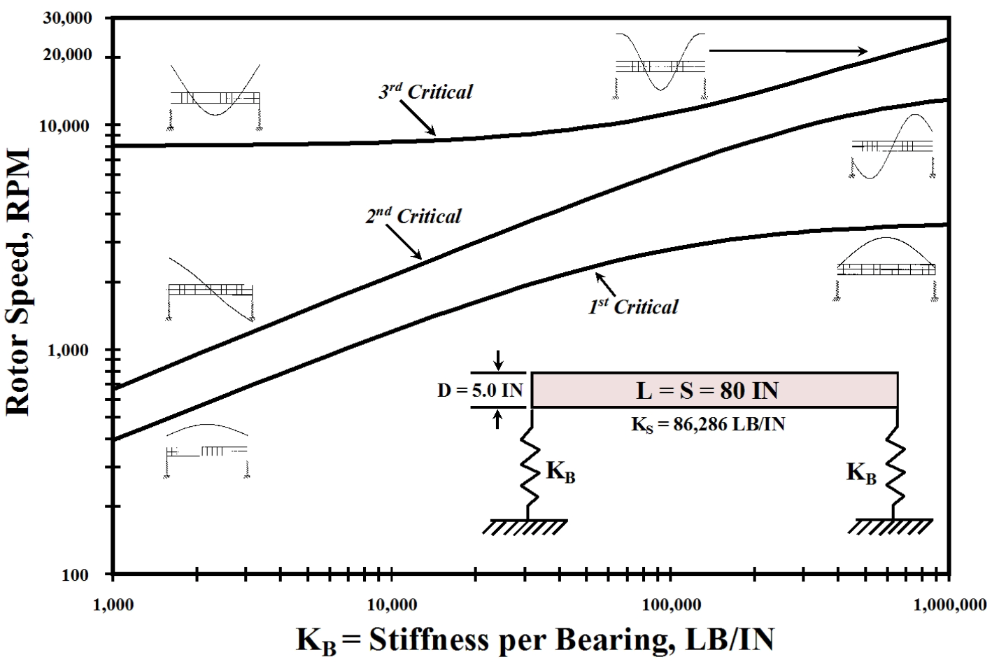
I am trying to use ROSS to get mode shapes similar to Figure 7 in A Practical Guide to Rotor Dynamics. The mode shapes I'm trying to generate are on the right side of this figure:
This is for a solid steel shaft with a bearing at each end. The parameters I'm using for the model are: My example code for a bearing stiffness of 10^6 lbf/in (1.75126 x 10^8 N/m) is shown below. import ross as rs
# Steel material properties
steel = rs.Material(name='Steel', rho=7810, E=211e9, G_s=81.2e9)
# Number of shaft elements
N_elem = 6
# Dimensions of a shaft element
L_total = 2.032
L = L_total / N_elem
i_d = 0
o_d = 0.127
shaft_elem = rs.ShaftElement(
L=L,
idl=i_d,
odl=o_d,
material=steel,
shear_effects=True,
rotary_inertia=True,
gyroscopic=True
)
shaft_elements = [shaft_elem for _ in range(N_elem)]
# Bearings at beginning and end of shaft
bearing0 = rs.BearingElement(n=0, kxx=1.75126e8, cxx=0)
bearing1 = rs.BearingElement(n=N_elem, kxx=1.75126e8, cxx=0)
bearings = [bearing0, bearing1]
# Rotor assembly
rotor = rs.Rotor(shaft_elements=shaft_elements, bearing_elements=bearings)
fig = rotor.plot_rotor()
fig.show()
# Run modal analysis and store results
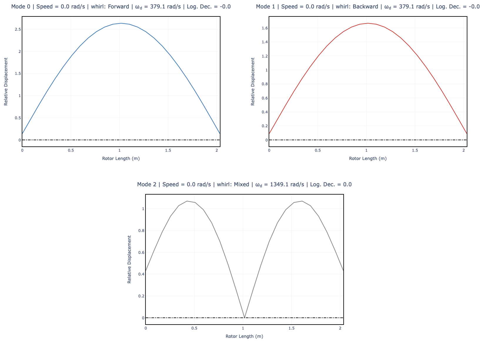
results = rotor.run_modal(speed=0)
# Plot 2D results using ROSS
fig = results.plot_mode_2d(mode=0, width=800, height=600) # mode 1
fig.show()
fig = results.plot_mode_2d(mode=1, width=800, height=600) # mode 2
fig.show()
fig = results.plot_mode_2d(mode=2, width=800, height=600) # mode 3
fig.show()The generated plots for the 1st, 2nd, and 3rd mode shapes are shown below. The 2nd and 3rd mode shapes are not similar to the shapes shown in Figure 7 from the reference mentioned above. Am I using the correct mode values, for example, is
|
Beta Was this translation helpful? Give feedback.
Replies: 1 comment 5 replies
-
|
Hi @wigging !
Yes,
The speed in modal analysis impacts the results in two ways:
The gyroscopic effects can cause the backward and forward modes to 'split.' By adjusting the speed (e.g. As for
This option to plot the 'y' values is not exposed to the user for now. I will open an issue to implement that. |

Beta Was this translation helpful? Give feedback.
-
|
So how did you plot Y axis values if they are not available? Is it yn in the Shape object? |
Beta Was this translation helpful? Give feedback.
-
|
Also, what are the units associated with the Relative Displacement axis? |
Beta Was this translation helpful? Give feedback.
-
|
It looks like I can get to the y axis values with |
Beta Was this translation helpful? Give feedback.
-
|
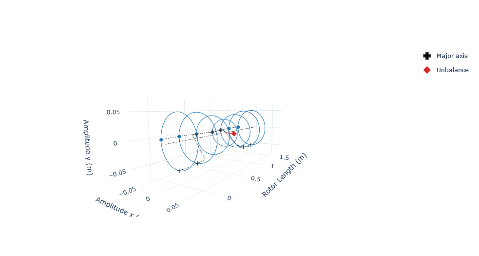
Yes. Soon we will make the orientation argument available to the If we run an unbalance response analysis, then we have a ‘deflected’ shape which will have ‘actual’ displacements. For example, this code: import ross as rs
import numpy as np
rotor = rs.rotor_example()
frequency_range = np.linspace(315, 1150, 101)
results = rotor.run_unbalance_response(
node=3,
unbalance_magnitude=3,
unbalance_phase=0,
frequency=frequency_range,
)
results.plot_deflected_shape_3d(speed=frequency_range[4])will produce this deflected shape:
In this plot, we have ‘meter’ as the displacement unit. This deflected shape is mainly influenced by:
|
Beta Was this translation helpful? Give feedback.
-
|
Ok, thanks again for the help. I look forward to the addition of the orientation argument to the |
Beta Was this translation helpful? Give feedback.
Hi @wigging !
Yes,
mode=0represents the first mode shape. However, note that in this scenario,mode=0andmode=1are quite similar, with mode=0 being the first backward mode andmode=1being the first forward mode. The terms backward and forward pertain to rotor whirl, which can occur in the same direction as the rotation (forward) or the opposite (backward). In the context of the undamped critical speed map you provided, discussions typically revolve around forward modes. As a result, the first plot on the right side of the figure corresponds tomode=1.