Assembly
##XY Motor Assembly
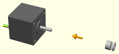
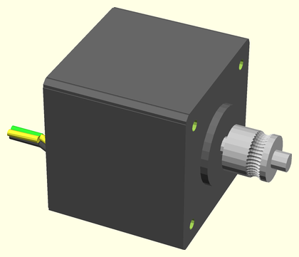
Press-fit a drive gear onto the shaft of a stepper motor, making sure to align the flat of the shaft with the flat of the shaft hole. Repeat this with the other drive gear and another stepper.
| Before | After |
|---|---|
 |
 |
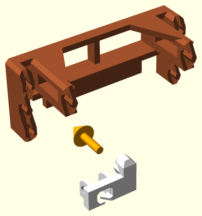
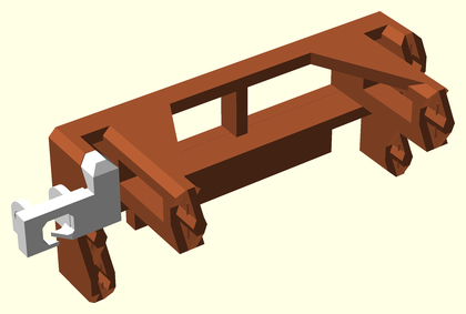
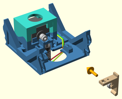
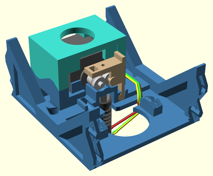
##Motor Mount Assembly
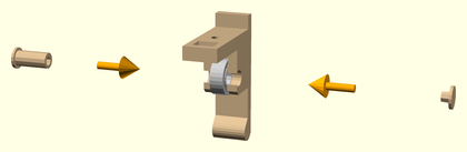
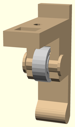
Attach a limit micro-switch (with wiring) to one of the side clips, with the lever end towards the center. Do this again for a second switch and mount plate.
| Before | After |
|---|---|
 |
 |
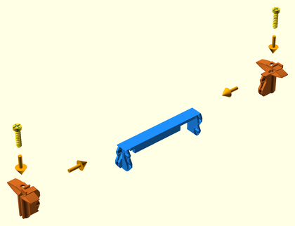
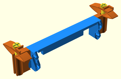
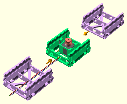
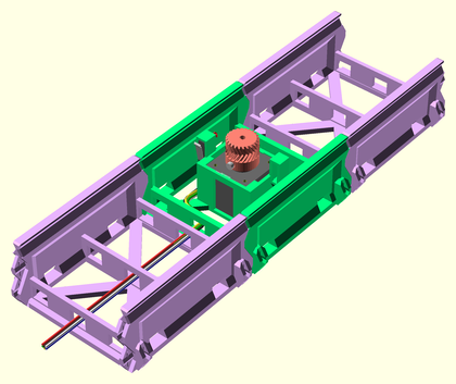
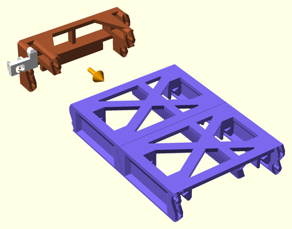
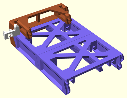
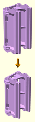
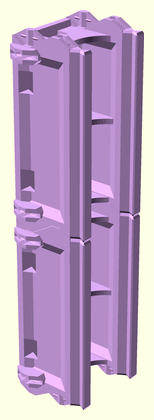
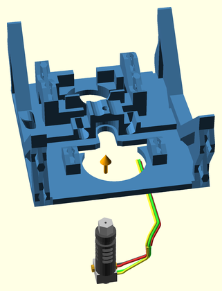
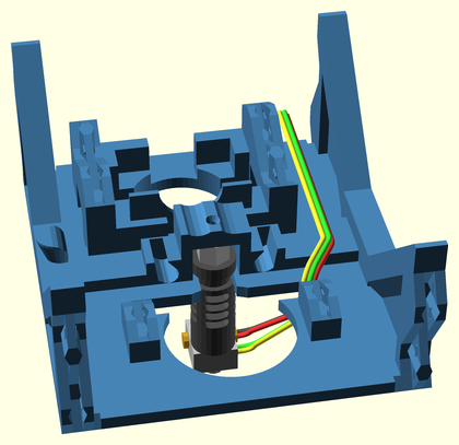
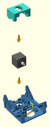
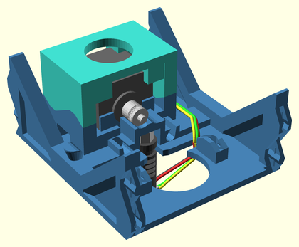
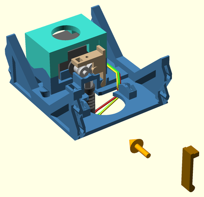
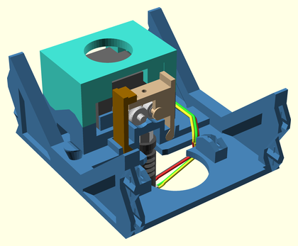
##XY Motor Segment Assembly
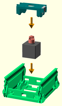
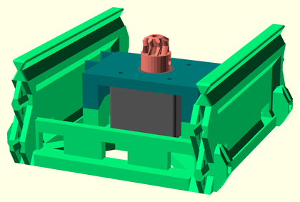
Seat the stepper motor with drive gear in the X/Y motor rail segment. Clamp it into place with a motor mount plate with micro-switch. Repeat this to make a second XY motor segment assembly.
| Before | After |
|---|---|
 |
 |
##Y Axis Assembly
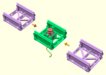
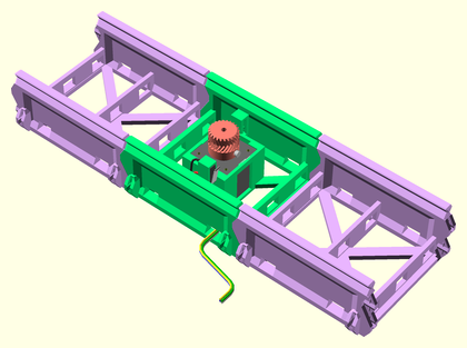
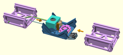
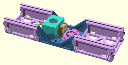
Join a rail segment to each end of another motor rail assembly. Route wiring out the side wiring access hole on the motor rail segment.
| Before | After |
|---|---|
 |
 |
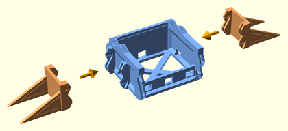
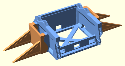
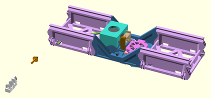
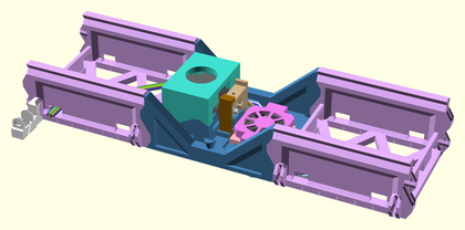
Join opposing platform supports to either side of the sled endcap. Point the tabs toward the side with the joiners.
| Before | After |
|---|---|
 |
 |
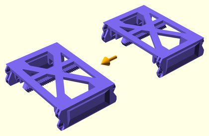
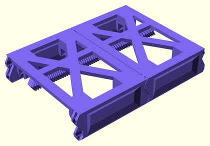
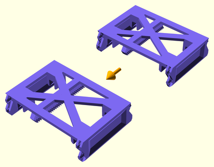
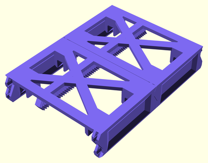
Join two XY sled parts together. Make sure the bottom racks line up.
| Before | After |
|---|---|
 |
 |
Join a Y sled endcap assembly to one end of the Y sled central assembly.
| Before | After |
|---|---|
 |
 |
Slide the Y sled partial assembly onto the Y axis rails assembly, so that it is centered.
| Before | After |
|---|---|
 |
 |
Join the other Y sled endcap assembly to the end of the Y sled partial assembly.
| Before | After |
|---|---|
 |
 |
Join a rail endcap to each end of the Y axis with completed sled assembly.
| Before | After |
|---|---|
 |
 |
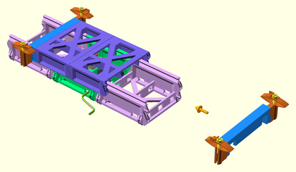
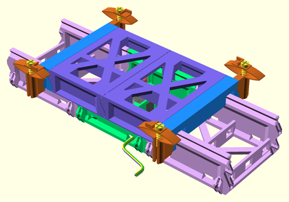
##X Axis Assembly
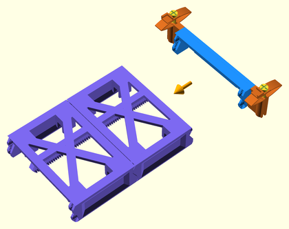
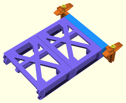
Join a rail segment to each end of a motor rail assembly, to make the X axis slider. Route the wiring to one end of the slider assembly.
| Before | After |
|---|---|
 |
 |
Join two XY sled parts together. Make sure the bottom racks line up.
| Before | After |
|---|---|
 |
 |
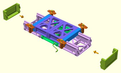
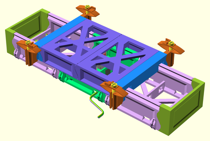
Join an X sled endcap assembly to one end of the X sled central assembly.
| Before | After |
|---|---|
 |
 |
Slide the X sled partial assembly onto the X axis rails assembly, so that it is centered.
| Before | After |
|---|---|
 |
 |
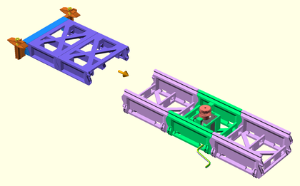
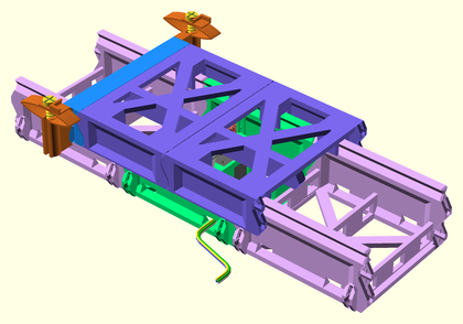
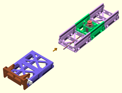
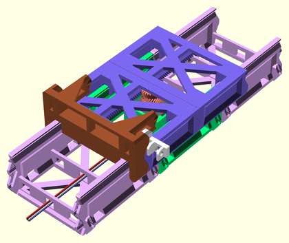
Connect the Y axis assembly to the XY joiner on the X axis partial assembly.
| Before | After |
|---|---|
 |
 |
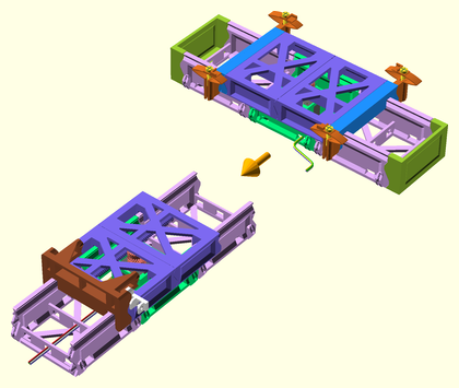
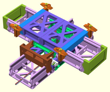
Join the other X sled endcap assembly to the end of the X sled assembly, fixing the Y sled assembly in place.
| Before | After |
|---|---|
 |
 |
##Z Tower Assembly
Seat the stepper motor in the Z motor rail segment. Clamp it into place with a motor mount plate without micro-switch. Repeat this to make a second Z motor segment assembly.
| Before | After |
|---|---|
 |
 |
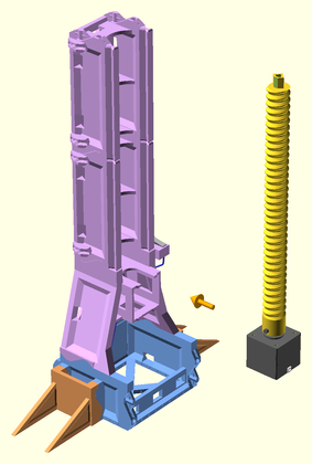
Screw the lock nut onto the threaded rod.
| Before | After |
|---|---|
 |
 |
Screw the rod into the coupler fully, then tighten the lock nut up against the coupler.
| Before | After |
|---|---|
 |
 |
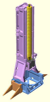
Press-fit the lifter rod assembly to the mounted motor shaft. Make sure the flatted side of the shaft is aligned with the flat of the shaft hole. Repeat this with the other Z motor segment assembly.
| Before | After |
|---|---|
 |
 |
Attach two rail segments to the top of the motor Z lifter assembly. Repeat this with the other motor Z lifter assembly.
| Before | After |
|---|---|
 |
 |
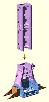
Attach support legs to each side of the yz_joiner part.
| Before | After |
|---|---|
 |
 |
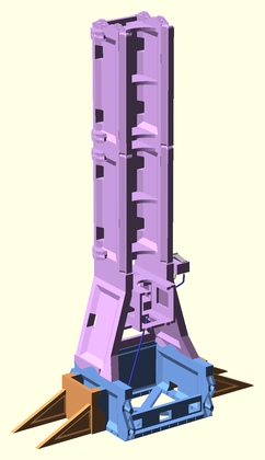
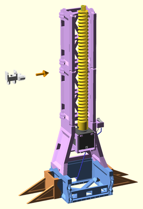
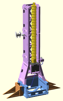
Attach the Z rail assembly to the top of the YZ joiner assembly.
| Before | After |
|---|---|
 |
 |
##Extruder Bridge Assembly
Insert the 686 bearing into the extruder idler arm.
| Before | After |
|---|---|
 |
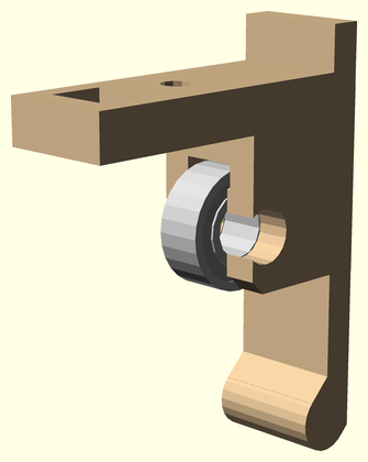 |
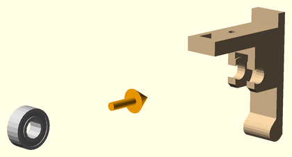
Insert the idler axle through the 686 bearing, and lock it into the extruder idler arm with the axle cap.
| Before | After |
|---|---|
 |
 |
Attach the extruder drive gear onto the stepper motor shaft.
| Before | After |
|---|---|
 |
 |
Slide the JHead extruder hot end into the slot in the bottom of the JHead platform.
| Before | After |
|---|---|
 |
 |
Clip the extruder motor with drive gear to the jhead platform using the extruder motor clip.
| Before | After |
|---|---|
 |
 |
Insert the idler arm into the idler hinge hole on the JHead platform.
| Before | After |
|---|---|
 |
 |
Insert the idler latch arm into the latch hinge hole on the JHead platform.
| Before | After |
|---|---|
 |
 |
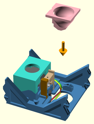
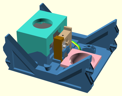
Insert the extruder fan shroud into the JHead platform, latching the JHead hot end, and idler and latch arms into place.
| Before | After |
|---|---|
 |
 |
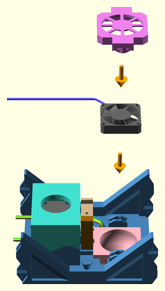
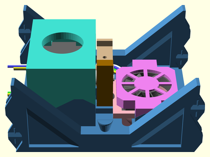
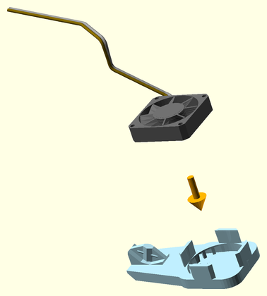
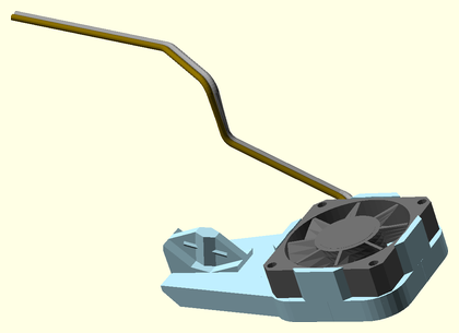
Clip a cooling fan to the top of the extruder fan shroud using the extruder fan clip part.
| Before | After |
|---|---|
 |
 |
Attach a cooling fan to the cooling fan shroud.
| Before | After |
|---|---|
 |
 |
Attach the cooling fan shroud assembly to the bottom of the extruder fan shroud.
| Before | After |
|---|---|
 |
 |
Attach rail segments to either end of the extruder platform assembly.
| Before | After |
|---|---|
 |
 |
Attach rail segments to either end of the extruder platform assembly.
| Before | After |
|---|---|
 |
 |
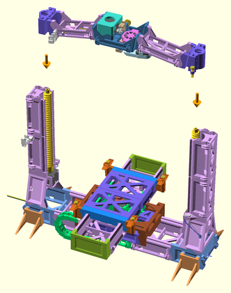
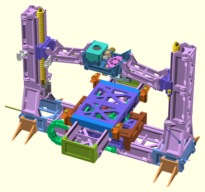
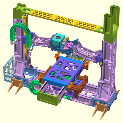
##Final Assembly
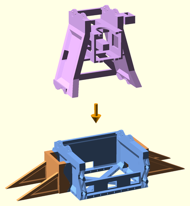
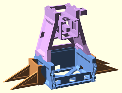
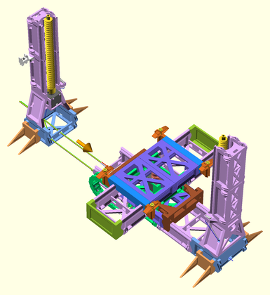
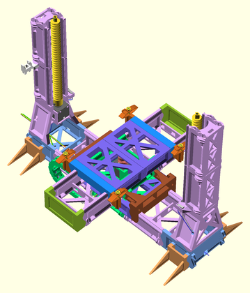
Attach the two Z tower assemblies to either end of the XY axes assembly.
| Before | After |
|---|---|
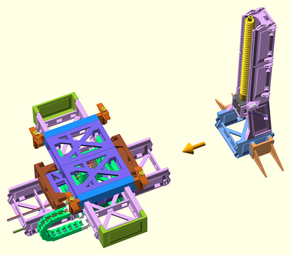 |
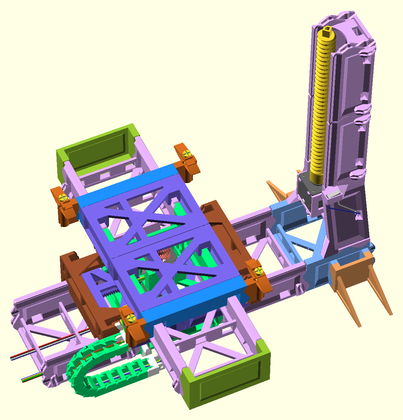 |
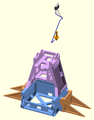
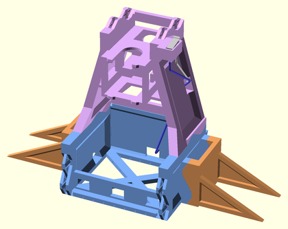
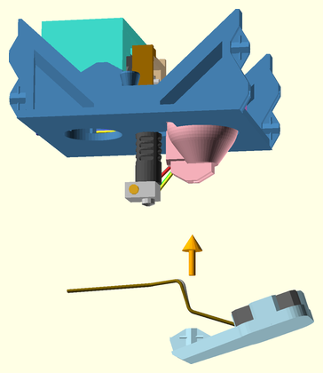
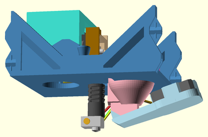
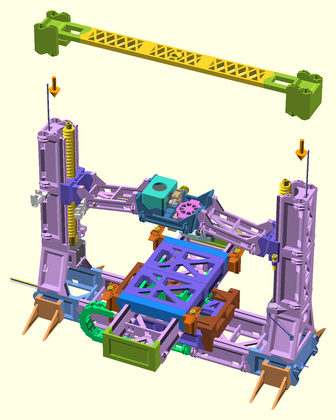
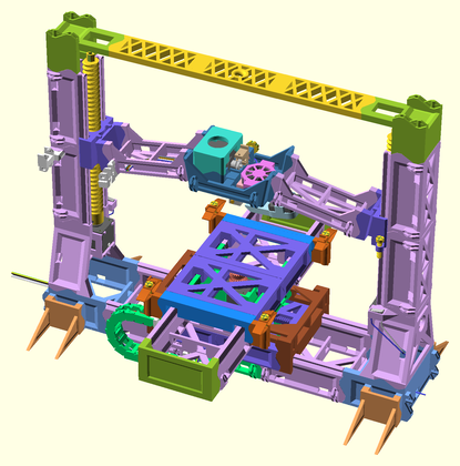
Lower the extruder bridge down into the Z tower grooves, screwing the lifter rods into the Z sleds evenly.
| Before | After |
|---|---|
 |
 |
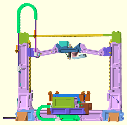
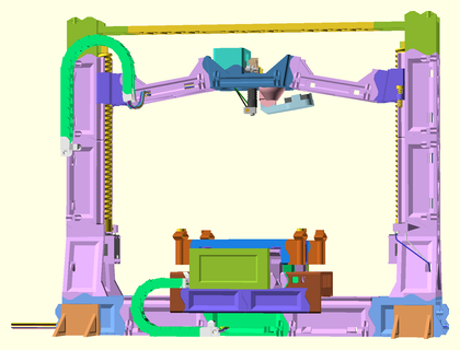
Attach the Z tower endcap.
| Before | After |
|---|---|
 |
 |
Attach the spool holder to the top of the other Z tower.
| Before | After |
|---|---|
 |
 |
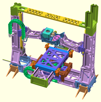
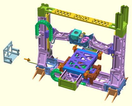
Attach the RAMPS motherboard mount to the end of the printer base.
| Before | After |
|---|---|
 |
 |
Clip the glass build platform to the build platform supports using four binder clips.
| Before | After |
|---|---|
 |
 |
Cradle the spool axle in the spool holder top.
| Before | After |
|---|---|
 |
 |