This repository covers the complete development and testing of an open-source soft robotics platform developed at the School of Electrical Engineering, University of Belgrade in Serbia (https://www.etf.bg.ac.rs).
The main goal of this project was to develop a low-cost modular platform for testing different highly elastic soft robot continuum shapes and different actuator mechanisms. This platform was primarily used to test tendon-driven soft robots, both with internal and external tendon routing. This repository contains all of the necessary files for anyone to recreate this project. This includes:
- Software for the Actuators, Robot Controller, and Python Scripts for controlling the Robot over Serial
- Gerber files for the Actuator PCBs
- CAD files for the actuators and the main soft robot construction
- CAD files for 2 different silicone molds used for casting the soft robots
Besides this GitHub repository, there is a Google Sheet with the complete BOM for the Actuator PCB, known Errors, as well as the API and the implemented commands. You can find the sheet here: https://docs.google.com/spreadsheets/d/1j4l9SDbZnH_yYO-BC3xJZ4RkYJjM1L0_M2_zAHDFm0k/edit?usp=sharing
If you're trying to recreate a part of this project and you're stuck somewhere or some files are missing, feel free to contact me! Email: [email protected]


To see how the robot looks in motion, click on the picture below, which will take you to the YouTube video, or click this link (https://www.youtube.com/watch?v=fuDRdF3EgcY)
Before the development of this project, a requirement list was put together to guide the project in a single direction.
- Ability to test different shapes and sizes of continuum shapes
- Ability to test highly elastic soft robots
- Precise force control tendon actuators
- Multiple actuator setup
To satisfy the first two conditions, the frame of the robot was made using aluminium 20x20 extrustions. This enabled the maximum modularity and configurability of the system while still keeping everything sturdy. In this way, different actuators can be mounted using a few screws, and the same goes for different continuum shapes.

To make the testing of different shapes even more straightforward, a plate and plate holder were designed and 3D printed so that different continuum shapes can easily be tested. In the pictures below, you can see the shape of the plate holder that attaches to the main frame. Soft robot bodies are cast with the plate attached to them and can then be easily attached to the plate holder with a couple of machine screws. This allows for easy testing of different continuum shapes by simply editing the CAD model of the plate to have the silicone anchors in the right places.


The plates shown above are designed for silicone continuums that are cast with the anchors inserted into the uncured silicone. Besides that, there are other options when using continuum shapes 3D printed out of TPU, for example. In the picure below, besides the silicone anchors, two additional methods can be seen for securing the continuum to the plate, one being with screws, and the other having a socket for glueing the continuum to the plate.

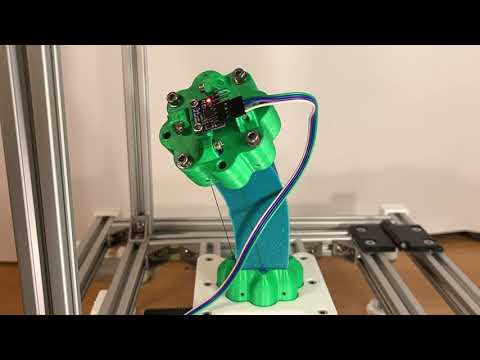
While the shore hardness of the silicone above is high enough for the silicone robot to stand on its own in the vertical position, the idea with this platform was to enable testing silicone rubbers with lower shore hardnesses as well. For those cases, the silicone rubber wouldn't be able to support itself, so an addition to this platform is that the angle of the central part of the frame can be changed, and a simple holder for the silicone robot can be added, as shown in the picture below.

A lot of time and effort was spent on the actuator design. The main goal for the actuators was, as stated above, to have precise force control. While current is directly proportional to the torque of the motor, the issue arises when the system needs to move from static to dynamic reference and vice versa, and also when there is a gearbox attached to the motor (sometimes with a lot of backlash). All of those things can cause issues with force control, which is why it was decided to measure the tendon force directly and close the control loop through the load cell measurement. The design of the final actuator is shown in the picture below.

A custom PCB was designed around the Raspberry Pi Pico as the MCU that controls a brushed DC motor using the DRV8842 motor driver. While a load cell is usually connected to an MCU using something like an HX711 24bit Sigma Delta ADC, this wasn't good enough for this use case since its maximum sample rate is 80SPS. Instead, the load cell was connected to an instrumentation amplifier, INA826, that could provide the necessary sample rate for the control loop. Since the amplification could be adjusted on the instrumentation amplifier using a potentiometer, a calibration method was needed to ensure accurate absolute measurements. This was done using a calibration stand that is described at the bottom of this Readme file. The gerber files for the PCB are available in the Actuators directory, and the PCB and electronics can be seen in the pictures below.


The motors that are shown in all of the pictures above and that were used for all of the tests are the Pololu 12V motors with 19:1 reductors (https://www.pololu.com/product/2822). These aren't the motors that need to be used, however, because the design of the actuators allows the use of any brushed DC motor (Up to 28V and 5A) by redesigning a single 3D printable part. Different motor setups with the same electronics can be seen in the picture below.

A single actuator can be used as a standalone unit by simply connecting a USB cable to the Raspberry Pi Pico. While this is easy to use for some simple tests, the goal was to be able to have multiple actuator setups. This is why both the hardware and software for these actuators were developed so that multiple of these actuators can be easily daisy-chained and controlled over I2C (Actuators have dual power connectors to enable daisy chaining, as well as multiple I2C connectors). In a multi-actuator setup, a Robot Controller Raspberry Pi Pico is needed that acts as the master device on the I2C bus.
The API for controlling the robot was designed to mimic the look of G Code commands, where a command number would be followed by space-separated parameters that are to be sent to the actuator(s). In a multi-actuator setup, these commands are sent to the Soft Robot Controller over Serial, which then translates those commands to I2C and sends them to all of the actuators. The Soft Robot Controller also plays a role in gathering the data from all of the actuators and from the IMU attached to the top of the robot. That data is saved into a CSV file and further analyzed after the tests are done. Some of the commands are shown in the table below
| Command | Name | Description | Command Format - Serial | Command Format - I2C | Parameters |
|---|---|---|---|---|---|
| C0 | Stop All | When the controller receives this command, it shuts down both PWM channels to 0% duty cycle, it disables the driver and turns off the enable LED | C0 | {0, 0, 0, 0, 0, 0, 0, 0, 0, 0, 0, 0, 0, 0, 0, 0} | None |
| C1 | Enable/Disable Driver (All) | When the controller receives this command, depending on the parameter, it will either enable or disable the driver, which will also be shown through the Enable LED on the PCB. Disabling the driver this way does not effect the PWM duty cycle like the C0 does | C1 1/0 | {1, X, 0, 0, 0, 0, 0, 0, 0, 0, 0, 0, 0, 0, 0, 0} | X = 1 - Enable X = 0 - Disable |
| C2 | Decay Mode | This command changes the decay mode on the DRV8842. For a detailed description of decay mode, refer to the datasheet of the DRV8842 motor driver. | C2 1/0 | {2, X, 0, 0, 0, 0, 0, 0, 0, 0, 0, 0, 0, 0, 0, 0} | X = 1 - Fast Decay X = 0 - Slow Decay |
| C3 | Change Mode (All) | This command changes the mode of the actuator; in this way, the algorithm structure can be changed for the controller itself. Mode 1 - Manual Control Mode 2 - PI Controller Load Cell Mode 3 - PI Controller IMU |
C3 X | {3, X, 0, 0, 0, 0, 0, 0, 0, 0, 0, 0, 0, 0, 0, 0} | X - Mode X |
| C4 | Manual Drive | This command enables driving the motor in one or the other direction by setting the PWM duty cycle manually as well as the motor direction. For this command to work, the motor driver needs to be enabled first; the command will not automatically enable the motor driver. If the direction is set to 3, only the PWM will be changed with the before chosen direction. | C4 DX SY | {4, X, Y, 0, 0, 0, 0, 0, 0, 0, 0, 0, 0, 0, 0, 0} | X - Direction parameter [1, 2, 3] X = 1 - Direction 1 X = 2 - Direction 2 X = 3 - Last direction Y - Speed [0 - 100] Y = Duty Cycle [%] |
| C5 | Set Force Reference | This command sets the reference of the PI Controller that closes its loop through the load cell. The reference is set in grams and can be anything between 0g and 10000g (0g to 1000g in safe mode). For I2C, the reference is calculated as: Reference = 255 * X1 + X2 |
C5 X | {5, X1, X2, 0, 0, 0, 0, 0, 0, 0, 0, 0, 0, 0, 0, 0} | X - Force reference [0-10000] X = X1 * 255 + X2 |
The table above shows some of the commands. The full list of commands and future commands that will be added can be found in the Google Sheet: https://docs.google.com/spreadsheets/d/1j4l9SDbZnH_yYO-BC3xJZ4RkYJjM1L0_M2_zAHDFm0k/edit?usp=sharing
In the pictures above, two different silicone rubbers are shown. The pink silicone rubber is Mold Max 30 silicone (https://www.smooth-on.com/products/mold-max-30/), which was mixed as per the manufacturer's instructions and degassed in a vacuum chamber before being poured into a mold. The green silicone rubber was an experiment using natural silicone rubber mixed with food dye to speed up the curing process before being poured into the mold. For testing the properties of the different silicones, a manual strain test apparatus was constructed for measuring the tensile strength of the different silicone rubbers.

Results that were made using this apparatus are shown in the two figures below.


CAD models for both of the molds can be found in the CAD directory. Since the plate had to stay attached to the silicone after taking it out of the mold. Special consideration was taken in designing these molds so that they can be disassembled around the soft robot, leaving the soft robot with the plates attached in the end.


As mentioned above, the actuator needs to be calibrated because the amplification of the instrumentation amplifier can be adjusted using a potentiometer. The calibration stand has a calibrated load cell at the top that is connected to the actuator using a tensioner and a spring. In this way, the force can be adjusted and kept at the desired force. The calibration stand and the calibration graph are shown in the pictures below.


This part will showcase some of the recorded results using this setup. The results shown here are with either one or two actuators, with an MPU6050 attached to the top of the robot. The measurements are done on the round Mold Max 30 silicone continuum. In the picture below, a sawtooth reference was sent to the actuator between 10N and 50N. This soft robot had internally routed tendons.

The angle measured at the top of the robot is shown in the figure below.

By looking at a rising edge of the single peak, we can try estimating a linear function to approximate the angle based on the force, as shown in the picture below.

Using the parameters of those lines, the comparison between the measured and estimated angles is shown in the figure below.

Using the parameters from the line calculated above, the estimated angle was calculated for a test where a sine reference was sent to the actuator.

The estimations weren't done for the two-actuator setup because there is coupling between the actuators; the actuators were placed at 90 degrees from each other. The results of those tests are shown below.

