SMD Wing
The SMD Wings board provides a complete solution for satellite uplink development.
It comes with the SMD module pre-soldered and pre-flashed with the latest firmware, ensuring out-of-the-box functionality.
Its Feather-compatible design enables rapid prototyping by seamlessly integrating with Feather boards, while streamlined testing ensures reliable Argos SMD connectivity. Designed with production in mind, this board simplifies the transition from prototyping to large-scale manufacturing with minimal hardware changes.
✅ Certified by CLS/CNES – the board can communicate with satellites with just a valid ID.
Request your ID from CLS and upload it to the board using a simple AT command.
This board is dedicated for use with Adafruit Feather boards and has been thoroughly tested with the nRF52840 Feather.
Versioning is managed via GitHub Releases and Tags.
-
Latest (02/2025):
-
V1.0 production (
branch breakout-v1.0)
-
V1.0 production (
- Dimensions: 51 × 30 mm
- Weight: 7 g
-
Power Supply: provided by Feather board
- Powered by USB or Battery (required for uplink)
- System voltage (3.3 V) required for core operation
- Tested with nRF52840 Feather, enabling BLE communication
- Reference design includes a dedicated LDO for the power amplifier
- u.FL connector and Pi-filter integrated
- On-board programmer
- Pinout provides easy access to Serial/UART for KimGUI communication
Below is a simplified explanation of the block diagram.
Dashed lines represent optional test connections available during development or debugging:
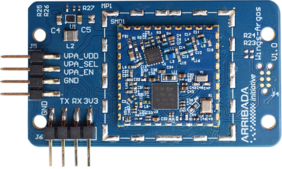
- External VPA Header (J5): Optional test access for PA power supply.
- Debugger Connector (J6): Easy serial/USB interface for CLS KimGUI software (AT command testing).
- Qwiic I²C Connector (J7): Expansion port for external I²C devices.
- Feather Headers (J1 & J3): Main interface to Feather boards.

Thanks to the Feather board, no external power supply is required.
A simple USB cable or battery connected to the Feather is sufficient.
🔗 nRF52840 Feather Power Management
It can also operate without a Feather if the user supplies:
- 3.3 V on J3-2
- GND on J3-4
- VBAT (J1-1) and/or USB (J1-3)
The 3.3 V required for Argos-SMD VDD comes from the Feather’s power regulator.
The PA amplifier is powered via the TPS63901 buck/boost converter.
- Input range: 1.8 V – 5.5 V
- Quiescent current: 75 nA
- Output: 3.3 V (400 mA, SEL = HIGH) or 1.8 V (SEL = LOW)
- Control: SEL pin managed either by SMD GPIOC1 or Feather D11
- Secondary voltage: adjustable via resistor R27
⏱ Startup time: ~2.375 ms to ramp up to 3.3 V (soft-start).
Each pin from the Feather headers is routed through a 0-Ω resistor.
By default, only UART and Wake-up signals are actively connected.
The Feather provides:
- 3.3 V power
- USB/Battery input voltage
- Direct communication signals

Provides access to:
- VDD_PA
- VPA_SEL (1 → 3.3 V default, 0 → 1.8 V disabled)
- VPA_EN
- GND
- Pins are mainly for monitoring.
- Controlled directly by STM32.
- Wing v1.0: missing pull-up (VPA_SEL) and pull-down (VPA_EN) → undefined states if STM is OFF.
- Wing v1.1: resistors added.
- VDD_PA directly connected to LDO output → cut PCB trace before injecting external voltages.
Provides external access to STM32 UART.
- 3V3, RX, TX, GND
Used for SMD module programming.
- Qwiic-compatible I²C port.
- Default: connected to Feather.
- To connect to SMD: populate R15 & R16.
- Not used by default.
- Experimental draft implementation available.
Connects the antenna to the satellite module.

The Wing communicates with the Feather via UART.
By default, two 0-Ω 0402 resistors must be soldered to enable communication.

By default, firmware uses PB3 (see main.c and lpm.c).
- Wing v1.0: PB3 used as SWO
- Wing v1.1: HW modification applied (see below)
- Remove R23 (0-Ω 0402)

- Populate R18 (0-Ω 0402)

Update main.h and connect appropriate resistors:
#define EXT_WKUP_BUTTON_Pin GPIO_PIN_3
#define EXT_WKUP_BUTTON_GPIO_Port GPIOB
Update lpm.c to configure configWakeUpPins:
static void LPM_configWakeUpPins(void)
{
    HAL_PWR_DisableWakeUpPin(PWR_WAKEUP_PIN1);
    HAL_PWR_DisableWakeUpPin(PWR_WAKEUP_PIN2);
    HAL_PWR_DisableWakeUpPin(PWR_WAKEUP_PIN3);

    __HAL_PWR_CLEAR_FLAG(PWR_FLAG_WU);

    HAL_PWR_EnableWakeUpPin(PWR_WAKEUP_PIN3_HIGH);
}In some scenarios, you may wish to operate the Wings-SMD board without a Feather host MCU (e.g., for testing or custom integration). This is considered an advanced/unsupported configuration and requires hardware modifications (a dedicated standalone board coming soon).
If you can provide a stable 3.3 V supply directly to the breakout board, the onboard LDO regulator will continue to power the PA (Power Amplifier) in this mode.
- Supply 3.3 V and connect RX/TX/GND through J6 for communication with your MCU.
- The onboard power path remains unchanged, simplifying setup.

For more advanced testing, it is possible to bypass the breakout board’s LDO and power the PA externally using J5.
Steps:
-
Cut the option pad that connects the LDO output to the PA power line.
(This isolates the onboard regulator from the PA.) - Provide your external PA supply via J5.
- J5 pins: VDD_PA, VPA_SEL, VPA_EN, GND
This configuration ensures the PA is powered only by your external source, not the onboard LDO.

✅ Summary:
- Use J6 if you just want to supply 3.3 V and access UART (simplest method).
- Use J5 if you need full control over the PA supply rail (advanced method).
The Wings-SMD (with SMD module) is pre-flashed with:
argos-smd-at-kineis-firmware
To update or reprogram:
- Requires TC2030-IDC-NL connector (No Legs)
- Compatible with J-LINK Edu Mini or ST-LINK
- For development: use a TC2030 clip to secure the programmer.
You can use SEGGER JLink Lite to flash, or re-flash, an Arribada SMD Wing board with updated firmware.
- Download the J-Link "J-Link Software and Documentation pack" - https://www.segger.com/downloads/jlink/
- Connect your J-Link via USB to your computer
- To verify that your J-Link is connected correctly and that your TC2030-NL cable is plugged in correctly, open the software J-Flash and create a new project. Select STM32WL55JC_M4 as your target and leave the Target Interface at SWD, 4000 kHz
- Select Target > Connect
- Verify that you see "Connected Successfully" as the last output in the on-screen Log. If you do, proceed to the next step, otherwise confirm the orientation of your J-Link cabling. Note - the Feather also needs to be powered with a battery when flashing, as it passes 3v3 power through the SMD you are attempting to flash on the Wing.
- Now that your connection is verified, open the Segger software J-Link Lite and select the same target device, interface and speed as above.
- Select the argos-smd-at-kineis-firmware.hex file found in the firmware ZIP
- Click program.
See dedicated Wiki pages for details:
- SMD Module firmware (Kineis stack)
- Arduino test code for Feather nRF52840
- Zephyr SMD driver (coming soon)
-
CLS KimGUI (request from CLS) – AT command interface for SMD
Version ≥ 4.1.2 -
CLS Emulsat (request from CLS) – Satellite communication test with Adalm-PLUTO SDR
Version ≥ 0.9