The questions fundamental to this project are as follows: How can we automate indoor thermal imaging? How can we predict thermodynamic changes to an enclosed space resulting from changes made to a building?
The ultimate purpose of this project is to create an UAV capable capable of collecting and analyzing large data sets. Specfically, the drone should be able to take distance measurements in various directions for navigation and localization. Also, the drone must be able to capture ambient air-temperature readings and wall-temperature readings. Finally, the drone must collect visual images for 3D-modeling and thermal composite imaging.
Once all data collection tools are fully-functional, the UAV will collect differentiated data sets for wall temperatures and air temperature. Furthermore, data would be collected before and after thermal modifications were made to a room. This will allow a machine learning model to predict thermal changes to a room based on deliberate modification to the room's physical structure. These predictions would likely be displayed through a 3-D model of the room comprised of visual and thermal images collected by the UAV.
So far, there are two primary applications for this technology. First, the UAV could become an essential tool for improving the thermal efficiency of industrial-sized factories. Currently, companies typically heat or cool factories through large heating units which are bolted to the ceiling and simply expected to heat a specific surrounding volume. This is not a scientific approach and often results in significant air-temperature fluxuations throughout the factory. Our technology will assist companies in optimizing selection and placement of heating and cooling units in factories through data collection and predictive modeling.
This technology could also provide homeowners with an affordable tool to improve the thermal efficiency of their home. Similar to in a factory setting, the UAV would help homeowners place heating systems to optimize their coverage. Furthermore, systematic thermal imaging would easily detect individual weaknesses in thermal insultation.
This research project is conducted through the MIT Research Laboratory of Electronics' Grossman Group. Key contacts are below:
- Nicola Ferralis (Research Scientist, Grossman Group)
- Jacob Feldgoise (Undergraduate, Carnegie Mellon University): [email protected]
- Adrian Butterworth (Undergraduate, Imperial College of London)
- Select & order parts
- Fly drone via python script from laptop
- Fly drone via Raspberry Pi
- Capture sonar data
- Capture temperature sensor data
- Record thermal images
- Record visual images
- Implement thermal camera composite imaging
- Implement object avoidance
- Photograph room with thermal camera via drone
- Devise indoor localization system to identify location of images and sensor readings
- Stitch thermal images into a 3D model
- Implement machine learning to predict temperatures changes based on captured data sets
We considered five primary criteria when choosing which drone to purchase: assembly/configuration time, payload capacity, size, price, and programmability. Based on these criteria, we selected the 3DR Solo for this project. The 3DR Solo was the best choice mostly because it features a MAVlink Python library called "DroneKit-Python".
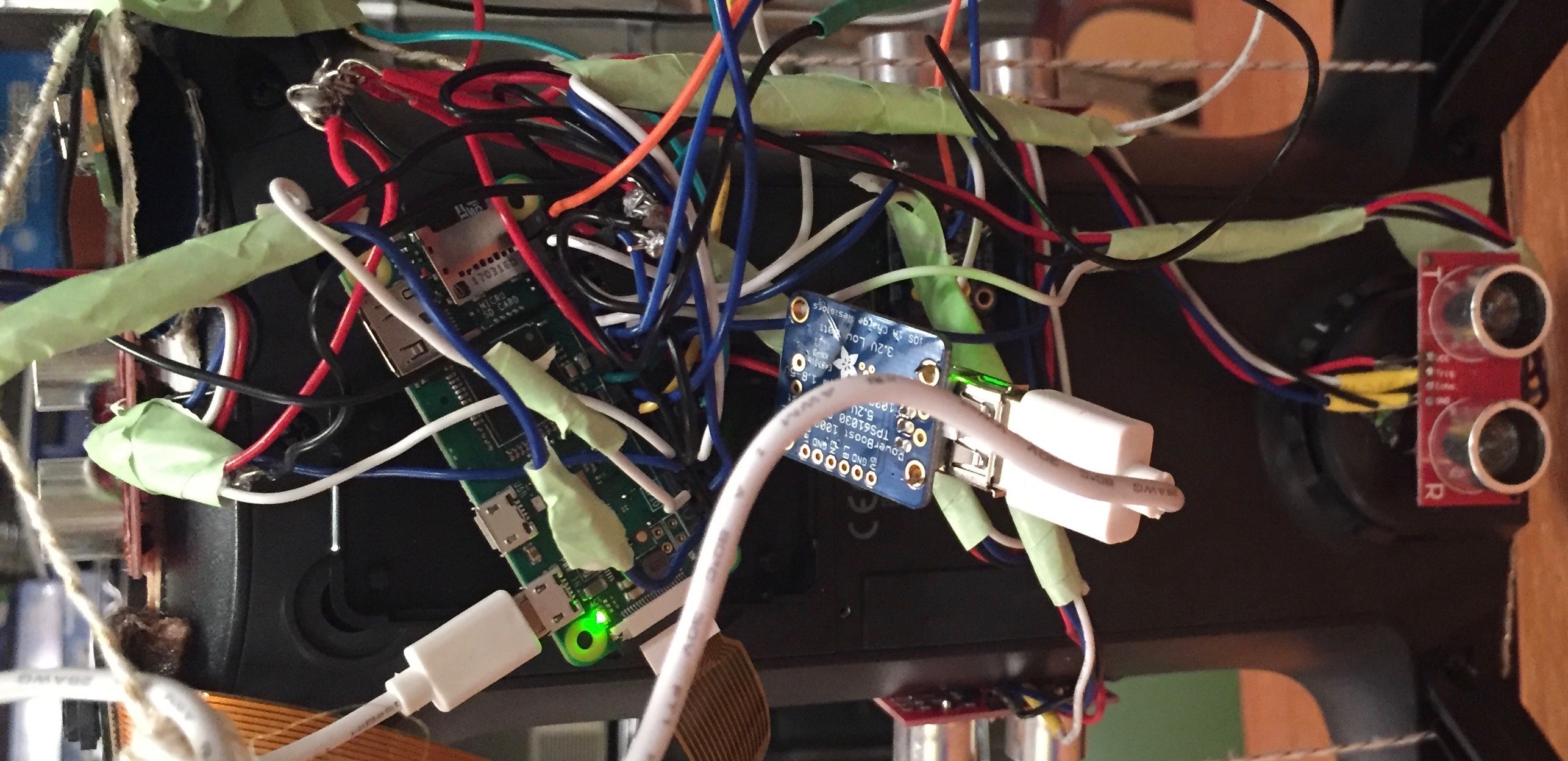
We used the Raspberry Pi Zero W as the onboard computer for this project. It is extremely light but still has the 40 GPIO pins of a full-sized Raspberry Pi. Also, the "W" model comes with intergrated wifi and bluetooth which is exteremly useful. Finally, the price of a Raspberry Pi Zero W is only $10. The only downside is that the Raspberry Pi Zero models lacks the processing power of the Raspberry Pi 3 Model B. Future projects should test the Raspberry Pi 3 to see if the additional proccessing power is worth its weight, literally.
The following sensors were used in this project:
- 6 Sonars (SR-04)
- 1 Temperature Sensor (BMP280)
- 1 Optical Camera (Raspberry Pi Camera Module v2)
- 1 Thermal Camera (Lepton FLiR)
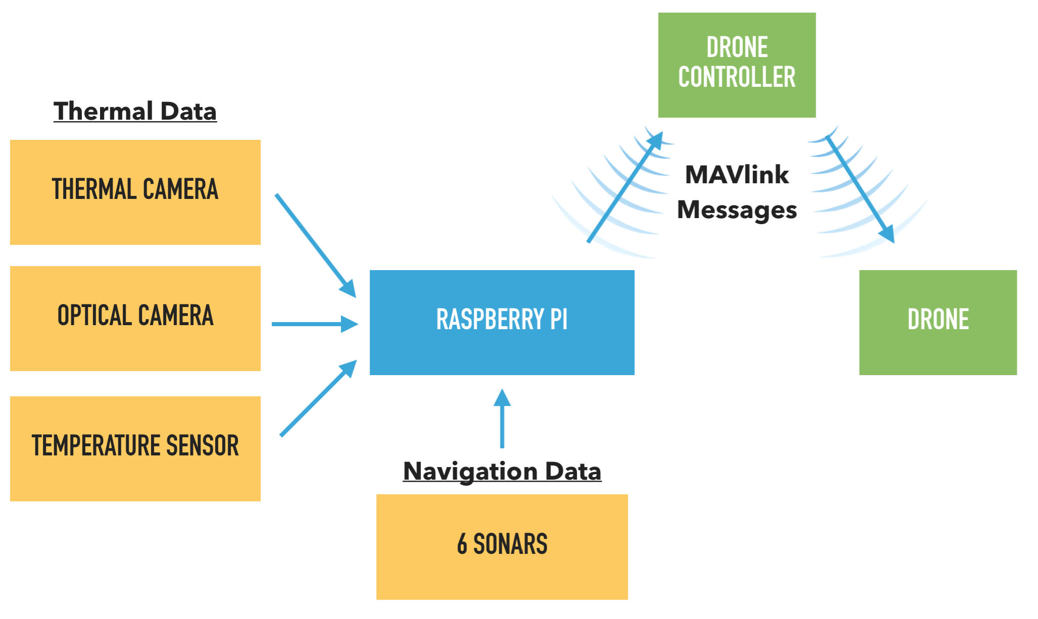
All the sensors mentioned in section 3.2 are directly wired into the Raspberry Pi's 40-pin GPIO board. The full pinout can be found below. The temperature sensor, optical camera, and thermal camera all provide information essential to the thermal data collection componant of the project. The sonars are primarily used for navigation and object avoidance.
The RPi inputs and processes the data from the 9 sensors, and then instructs the drone to take specific actions. These commands are sent from the RPi to the drone as MAVlink messages. These messages are transmitted via a wifi network broadcasted by the 3DR Solo's controller.
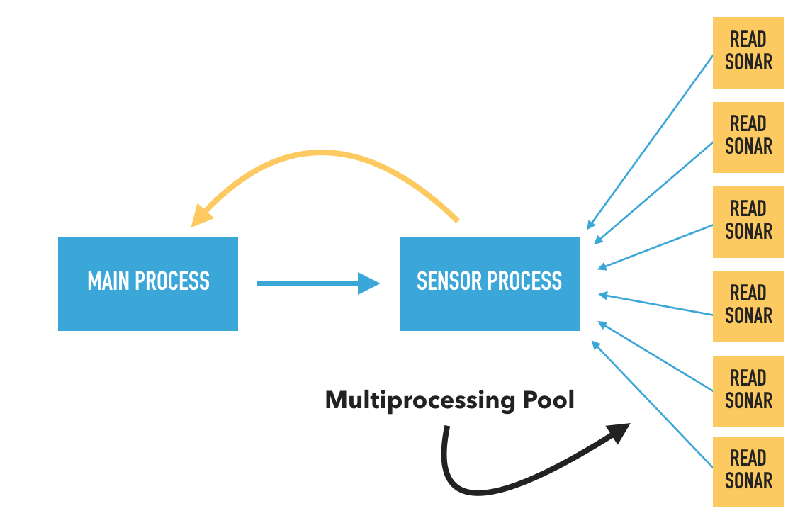
The most recently-updated sensor reading scripts for this project utilize multiprocessing. Implementation of multiprocessing, despite the RPi Zero's single core, has improved the read speed for all six sonars (SR-04) by over 10 times.
So far, numerous problems have impeded the development process. The majority of issues have originated from attempts to control the drone in a GPS-denied environment, but other issues exist as well.
DO NOT ATTEMPT THIS! DroneKit-Python is not yet compatible with the latest firmware release, so programming the drone in 1.5.2 is effectively useless. Hopefully, compatibility issues will be resolved in the future.
This project would be infinitely easier if we could utilize GPS in an indoor space. The 3DR Solo's ArduCopter firmware is primarily designed for GPS navigation and offers few good options for working in a GPS-denied environment.
GUIDED_NOGPS mode should theoretically allow the UAV to recieved GUIDED commands in a GPS-denied environment. However, tests using this mode have not yet succeded in controlled takeoff. I have not been able to determine the reason for failure.
STABILIZE mode is one of the most promising modes for flight in a GPS-denied environment because it holds the pitch and yaw such that the UAV remains level but allows for easy modification of the altitude. Also, STABILIZE mode does not require a GPS lock to initiate flight. However, STABILIZE mode does require that the thrust joystick is set to the lowest postion (not equilibirum) before initiating takeoff. This presents a seemingly insurmountable challenge for autonomous flight where the user should not need to touch let alone manipulate the controller.
RC overrides essentially involve sending MAVlink commands to the drone that act like transmissions from the controller. This is incredibly dangerous because it inpairs the controller's function as a failsafe in case of a severe drone malfunction. So far, we have not tested this option for navigation in a GPS-denied environment.
The viusal camera can malfunction when there is a faulty connection between the camera module and the RPi's camera port. This could be the result of a broken cable, but more likely, the camera module itself or the camera port are broken.
The best -- but most time consuming -- approach is to build a custom drone from scratch with all the neccessary sensors included in the original design. This is a feasible but unreasonable option given the current pace of the project.
A wired serial MAVlink connection between the onboard computer (Raspberry Pi) and the 3DR Solo drone would massively decrease communication latency and resulting issues. Such a connection would be routed through the 3DR Solo's Accessory Bay. This improvement would require manufactoring a custom breakout board for the Accessory Bay, which would then serve as the connection between the Raspberry Pi and the drone's Pixhawk autopilot hardware.
An Optical Flow Rangefinder is a module that points towards the ground and calculates distance through use of a high resoultion camera and 3-axis gyroscope. Therefore, Optical Flow ranges will be much more accurate than readings from $5 SR-04 sonars. Also, an Optical Flow Rangefinder can be used in calculations performed by the UAV's Extended Kalman Filter (EKF) if it is connected to the Pixhawk via the 3DR Solo's Accessory Bay.
The RPi Zero is an incredibly useful device for its size, but it is limited by its single-core processor and less-than-optimal processing power. A RPi 3 Model B will ultimately be worth the extra weight because it will be capable of taking sonar readings -- essential input for navigation -- at far greater speeds.
While sonars can be accurate, they are effectively useless beyond 1-1.5 meters. A potentially better localization system would include use of Ultra-wideband (UWB) beacons or a similar beacon-based technology.
Configuring the Raspberry Pi is fairly simple. We recommend using a MicroSD card of at least 16 GB. Please follow the directions below:
We will install Raspbian Stretch Lite, which means the Raspberry Pi will not use a GUI. Instead, you will communicate with the devie through the linux command line. To begin, download the software and follow the instructions on the Raspberry Pi website for your operating system.
Then, insert your MicroSD card into the Raspberry Pi and boot-up the device with a display, mouse, and keyboard attached. You should connect your Raspberry Pi to a display through a Mini HDMI cable (RPi Zero W) or regular HDMI cable (All other RPi's). The default username and password are "pi" and "raspberry" respectively. You should change the password, but the leave the username alone. To change the password, use the command passwd. You will need to authenticate the device, then enter your custom password as prompted.
Next, we will connect the Raspberry Pi to the internet. Please note that this step assumes you have a Raspberry Pi with an intergrated wifi module. Follow these directions and then restart the wifi interface with:
sudo wpa_cli reconfigure
Next, we will enable the following interfaces: SSH, SPI, IC2, Camera.
First, run the command: sudo raspi-config
Select "Interfacing Options", then go there enable SSH, SPI, and IC2, Camera. Then, exit out of the configuration tool and restart your Raspberry Pi. It is possbile that the computer will do so automatically. We will use SSH to connect to the Raspberry Pi during field tests. The SPI and IC2 interfaces must be enabled for the BME280 temperature sensor and FLiR camera to function. The Camera interface allows the optical camera to function.
We need to install a large number of python packages for the various aspects of this project towork. Please copy and paste the following commands into your Raspberry Pi's CLI, and hit "return" after each one.
First, we ensure all pre-installed packages and installers are up-to-date
sudo apt-get update
sudo apt-get upgrade
sudo python -m pip install --upgrade pip
sudo apt-get install build-essential python-pip python-dev python-smbus git
Then, we install the SciPy stack:
pip install --user numpy scipy matplotlib ipython jupyter pandas sympy nose
Next, we install a library to provide a cross-platform GPIO interface on the Raspberry Pi:
cd ~
git clone https://github.com/adafruit/Adafruit_Python_GPIO.git
cd Adafruit_Python_GPIO
sudo python setup.py install
Then, we install packages and software neccesary to run the BME280:
git clone https://github.com/adafruit/Adafruit_Python_BME280.git
cd Adafruit_Python_BME280
sudo python setup.py install
Then, we install packages for the Raspberry Pi optical camera:
pip install "picamera[array]"
Next, we install packages to support image processing (OpenCV) on the Raspberry Pi:
sudo apt-get install build-essential cmake pkg-config
sudo apt-get install libjpeg-dev libtiff5-dev libjasper-dev libpng12-dev
sudo apt-get install libavcodec-dev libavformat-dev libswscale-dev libv4l-dev
sudo apt-get install libxvidcore-dev libx264-dev
sudo apt-get install libgtk2.0-dev libgtk-3-dev
sudo apt-get install libatlas-base-dev gfortran
sudo apt-get install python2.7-dev python3-dev
wget -O opencv.zip https://github.com/Itseez/opencv/archive/3.3.0.zip
unzip opencv.zip
wget -O opencv_contrib.zip https://github.com/Itseez/opencv_contrib/archive/3.3.0.zip
unzip opencv_contrib.zip
pip install numpy
mkdir build
cd build
cmake -D CMAKE_BUILD_TYPE=RELEASE \
-D CMAKE_INSTALL_PREFIX=/usr/local \
-D INSTALL_PYTHON_EXAMPLES=ON \
-D OPENCV_EXTRA_MODULES_PATH=~/opencv_contrib-3.3.0/modules \
-D BUILD_EXAMPLES=ON ..
Now, before we move on to the actual compilation step, make sure you examine the output of CMake! Scroll down the section titled Python 2. Then make sure your Python 2 section includes valid paths to the Interpreter , Libraries , numpy and packages path. Now we will compile OpenCV. Please be aware that this process could take up to 4 hours to complete:
make
Once the compilation process has completed, run:
sudo make install
sudo ldconfig
Confirm that OpenCV has compiled correctly by running the following command:
ls -l /usr/local/lib/python2.7/site-packages/
You should see an output similar to the following:
total 1852
-rw-r--r-- 1 root staff 1895772 Mar 20 20:00 cv2.so
Next, we're going to install packages to run the FLiR Lepton:
sudo apt-get install python-opencv python-numpy
git clone https://github.com/groupgets/pylepton.git
cd pylepton
sudo python setup.py install
Finally, install the Dronekit-python package which will allow the Raspberry Pi to communicate with the 3DR Solo:
pip install dronekit
The last step is to connect the Raspberry Pi to the 3DR Solo drone. We do this by simply modifying the Raspberry Pi's wifi settings to connect to the controller's network.
The main purpose of your computer in the project is as a tool to edit, upload, and run python files on the onboard computer (Raspberry Pi). There are two steps to setting up your computer: installing a text editor and configuring SSH.
For Windows, we recommend using Notepad++. For Mac and Linux, we recommend using Atom.
For Windows, we recommend using PuTTY. For Mac, we recommend using the built-in UNIX command line. For Linux, we recommend using the built-in command line.
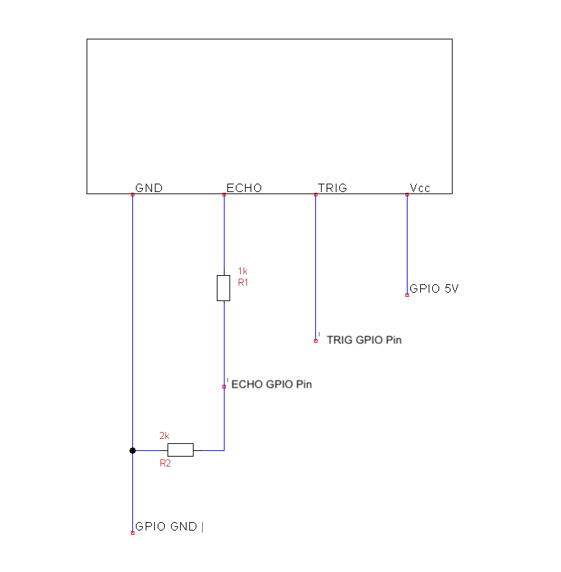
The current design uses six SR-04 sonars arranged to provided distance readings for the top, bottom, left, right, front, and back of UAV. The 5v pins of all six sonars can be wired together in parallel and connected to a single 5v GPIO pin on the Raspberry Pi. Similarly, ground pins of all six sonars can be wired together in parallel and connected to a single ground GPIO pin on the Raspberry Pi.
However, please pay close attention to the following diagram which converts the echo pin voltage for use with a Raspberry Pi. If you follow the pinout shown above than all sonars should work properly upon first use. If you modify the pinout in any way, the GPIO pin numbers will need to be adjusted in the script.
The current design uses a single Raspberry Pi Camera v2 to capture images in the visual spectrum. A 15cm ribbon cable connects the camera module to the Raspberry Pi. Please note that the camera module requires a special ribbon cable to work with the Raspberry Pi Zero models.
The current design includes a single BME280 Temperature, Humidity, and Pressure sensor. The device is mounted on the bottom of the UAV, however, future experiments should be conducted to determine the optimal location for such a sensor considering the decrease in local temperature caused by the UAV's propellers.
We will only connect four of the BME280's pins to the Raspberry Pi. Please reference the following list and the pinout in section 6.1.1:
- The 5V pin on the BME should connect to a 5V GPIO pin on the Raspberry Pi
- The SDI pin on the BME should connect to a SDA GPIO pin on the Raspberry Pi
- The SCK pin on the BME should connect to a SCL GPIO pin on the Raspberry Pi.
- The Ground pin on the BME should connect to a Ground pin on the Raspberry Pi.
The current design uses a Lepton FLiR to take thermal images of the UAV's surroundings and determine relative temperatures. The FLiR is mounted on the front of the UAV in close proximity to the Optical Camera in order to minimize the transformations needed to achieve thermal composite imaging. The camera itself is very small and incredibly delicate, so please be very careful when touching it. The camera module must be mounted in a breakout board which can then be connected to the Raspberry Pi. The FLiR module must be fully in the breakout board or it will not work properly. All 8 pins on the breakout board must connect to corresponding pins on the Raspberry Pi. The SDA and SCL pins should be wired in parallel to those from the BME280 and then connected to Raspberry Pi pins 3 and 5 respectively (see pinout).
Now that everything is configured, you can run a python program!
- Turn on the 3DR Solo controller and wait for it to boot up before continuing.
- Turn on the Raspberry Pi and ensure that it has been set to connect to the controller's wifi network. The Raspberry Pi should be connected to a portable power supply which is ideally attached to the 3DR Solo drone.
- Connect your computer to the controller's wifi network.
- Connect your computer to the Raspberry Pi via SSH. If you don't know the Raspberry Pi's IP address, use a tool like "Fing" to find it.
- Upload whichever python file you wish to run to the Raspberry Pi.
- Run the python program
filename.pyusing the following command:
python filename.py
Please be extremely careful while conducting field tests with untested code! Be sure to attach a rope to the drone to guide it in the event of a software failure. Also, always be prepared to use the "land" button on the controller.
- Altitude Hold Mode
- Autopilot Firmware Upgrade from 1.3.1 to 1.5.2
- Copter Commands in Guided Mode
- Create setter functions rather than setting attributes directly
- Move/direct Copter and send commands in GUIDED_NOGPS mode using DroneKit Python
- Guiding and Controlling Copter
- Indoor copter flight
- Indoor Flying Guidelines
- Quaternions
- QGroundControl User Guide
- 3DR Solo Development Area
- 3DR Solo User Guide
- DroneKit-Python Documentation
- API Documentation for PyMAVLink
- Python MAVLink interface and utilities
- Communicating with Raspberry Pi via MAVLink
- Companion Computers
- Solo Development Guide
- Mavlink (developer page)
- MAVLINK Common Message Set
- MAVLink Mission Command Messages (MAV_CMD)
- MavLink Tutorial for Absolute Dummies (Part I)
- MAVlink Message Definitions
- MAVProxy Landing Page
- MAVProxy Ardupilot Documentation
- MAVProxy Cheetsheet
- Operating Arducopter without GPS over MAVLink
- 3DR Solo Breakout Board Specs
- Vehicle State and Settings
- Which MAVLink commands can fly a copter without GPS?
- Basic Recipes
- Accessing the Raspberry Pi Camera with OpenCV and Python
- applyColorMap for pseudocoloring in OpenCV ( C++ / Python )
- Camera Module
- FLIR Lepton Hookup Guide
- Quick and dirty pure python library for interfacing with FLIR lepton
- How to install/use the Raspberry Pi Camera
- Image size (Python, OpenCV)
- OpenCV - Saving images to a particular folder of choice
- python OpenCV - add alpha channel to RGB image
- Install OpenCV 3 + Python on your Raspberry Pi
- Multiprocessing — Process-based parallelism
- An introduction to parallel programming using Python's multiprocessing module
- Communication Between Processes
- Multiprocessing with Python
- Multiprocessing vs Threading Python
- What does if name == “main”: do?
- Python 201: A multiprocessing tutorial


