Modifying the Lusya UPS
The Lusya UPS
Some of its hardware features are:
- Mounted from the bottom, power is transferred using a USB cable (provided together with mounting screws and spacers)
- Is sold with a 4.000mAh battery
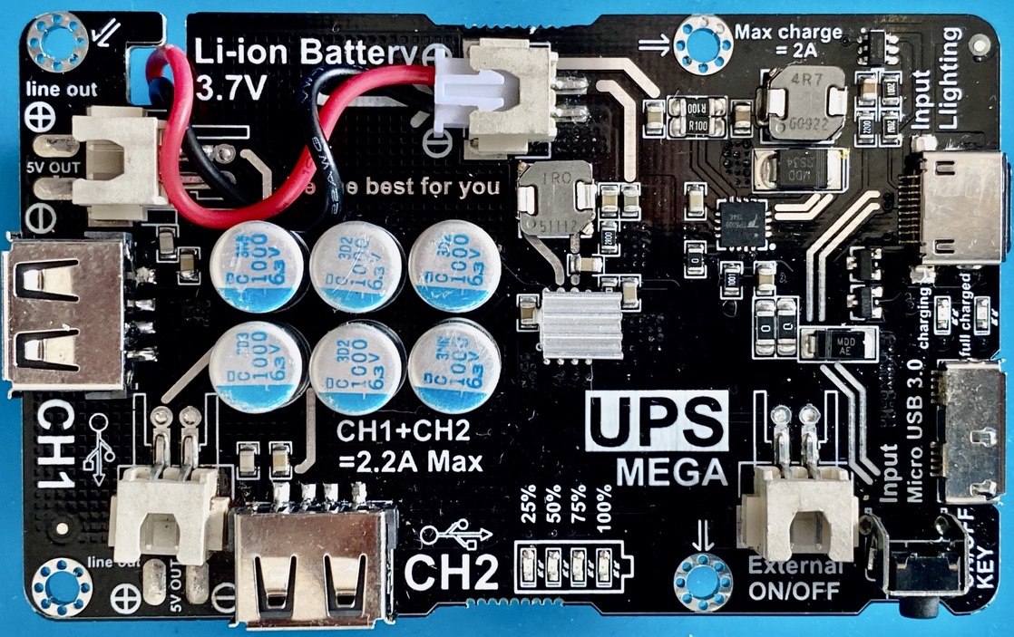
- The system is specified for a maximum current of 2.2A (i.e., I wouldn't use it for the RPi 4)
- It offers a connector for the switch (marked external, lower right in the picture)
- offers multiple outputs with different connectors (2 USB-A, 2 JST connectors, 2 solder pad connectors for your own cables)
- offers a USB Micro-B Superspeed connector (can be used as a normal USB Micro-B connector) for primary power
- offers a Lightning connector for primary power (as if you ever have an extra Apple charging cable...)
There is no way to turn the UPS off or on from the RPi, the only way is the black button that when pressed for a short time turns the UPS on and when pressed twice for a short time turns the UPS off (I had to implement additional functionality to reflect that). An alternative is to turn the UPS off is to press the button a very, very long time once (around 14 seconds).
The UPS turns off automatically if there is no or only a small power draw. This works quite well with normal RPi's, but the RPi Zero does not draw enough power to keep the UPS going. This means that the UPS cannot be used with a RPi Zero.
As often as I turned the power supply on and off, I was never able to let the RPi show that it measured any undervoltage. This is an excellent result (I’m quite harsh) and lets me trust this UPS to a large degree. I will, later on, provide oscilloscope measurements, but that is for another day.

The modification is extremely simple and minimal. Since this UPS already contains a connector for the switch, you don't have to solder that (you can if you prefer a permanent connection, solder it to the left side of the connector). So you only have to solder the cable that provides the battery power used to power the ATTiny.
Take a JST connector of the right size and optionally remove the connection on the right, if the connector is plugged in (see lower right of picture). The left connection (black cable in the photo) is the connection we need. Test by connecting to GND. If the UPS changes state then you got the right one.
Alternatively, you can solder a Dupont cable to the left connection on the connector (as it is marked in the picture).
In the upper middle of the picture the battery is connected. Cut a red Dupont cable to length and solder it to one of the marked areas, all of which are direct connections to battery power.
For the modified Lusya we need to „press“ the switch for 250ms to turn the UPS on and twice for 250ms to turn it off again. Depending on whether you used the jumper on the ATTiny Daemon PCB to connect the ATTiny to the RPi’s 5V power you can additionally let the system check the voltage (this is highly recommended). The config file entries for this are:
| Option Name | Default | Comment |
|---|---|---|
| ups configuration | 0x11|0x13 | This value configures how the ATTiny daemon tries to reset the system: Bit 0 = 1: Reset by „pressing“ a switch twice (pulling the line down for the reset pulse lenght turns the switch once) Bit 1 = 0: Do not check external voltage (external voltage is not connected to RPi Vcc) Bit 1 = 1: Check external voltage: (external voltage is connected to RPi Vcc) Bit 4-5 = 1: Add a second pulse to turn off the UPS Recommended for Lusya UPS is the value 0x13 (including connecting the EXT_V pin to the RPi Vcc via the jumper) |
| pulse length | 250 | This is the length of the pulse used to turn the UPS on and off |
| switch recovery delay | 1000 | This is the time in ms to wait before „pressing“ the switch again (needed since we are in switch mode) |