This tutorial shows how to build a music box (not only) for kids based on Raspberry Pi and NFC tags. The software is mainly based on Volumio which is a very nice music player distribution for the Raspberry Pi. Another small piece of software called MFRC522-trigger detects NFC tags with a NFC reader and triggers certain actions in Volumio (e.g. play playlists, stop playback).
If you have the impression that the how-to is unclear in certain parts or you're missing something, feel free to write an issue or simply create a pull request. Helping hands are highly appreciated.
- nfc-music-box
- Hardware
- Software
- Download, install and configure Volumio
- Enable volumio ssh access
- Install the MFRC522-trigger NFC Reader Software on your Volumio
- Copy Content to your Music Box
- Create Playlists from you Content
- Configure MFRC522-trigger to trigger a Volumio Playlist
- Trigger certain actions via GPIO buttons and gpio-trigger
- Archive
As of Version 4, Volumio dropped support for Raspberry Pi 1 and Raspberry Pi Zero (W). I suppose this is due to an older hardware architecture. Raspberry Pi 1 and Raspberry Pi Zero (W) have CPUs with 32bit ARMv6 architecture whereas newer Raspberry Pi models use 64bit ARMv8 architecture. The first version of the Raspberry Pi 2 is a bit of an exception since it has a 32bit ARMv7 architecture (haven't tried to install Volumio OS 4 on one of these). Also see this detailed Raspberry Pi Hardware models overview.
My original build in fact used a Raspberry Pi Zero W. Due to the limitation of Volumio OS 4, I had to replace the Raspberry Pi Zero W with a Raspberry Pi Zero 2 W. I stuck with the (newer) Zero model since my build is portable and the Pi Zero 2 W still has the lowest power consumption compared to all other newer models.
Please note that this hardware limitation only applies to Volumio OS. The other software part of this project MFRC522-trigger doesn't have this limitation. So if you just want to detect NFC tags and control/trigger something different than Volumio, feel free to also use older Raspberry Pi models.
| Item | Picture | Price (EUR) | Links |
|---|---|---|---|
| Raspberry Pi Zero 2 W |  |
17.90 - 22.00 | |
| Multi-pin Connector |  |
0.40 | |
| MicroSD Card (min. 8GB) |  |
7.00 - 15.00 | |
| RC522 NFC Reader |  |
2.40 - 6.49 | |
| NFC Tags |  |
0.30 - 1.10 | |
| Hifiberry MiniAmp |  |
21.90 - 23.70 | |
| 2x Speakers 3W |  |
4.90 - 9.45 | |
| Speaker Cable |  |
Optional. Simple copper wire might be enough for 3W speakers. | |
| Powerbank (pass-through charging) |  |
15.00 - | |
| 2x E Capacitor 4700 µF 6.3V | 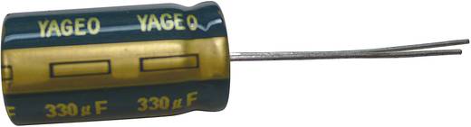 |
0.25 - 1.00 | |
| Inductor 33 µH 1,5A |  |
0.41 | |
| Micro-USB Power Supply |  |
6.99 - |
|
| Micro-USB Jack |  |
3.10 | |
| 4x Spacer 10mm |  |
0.92 | |
| 8x Screw 5mm | 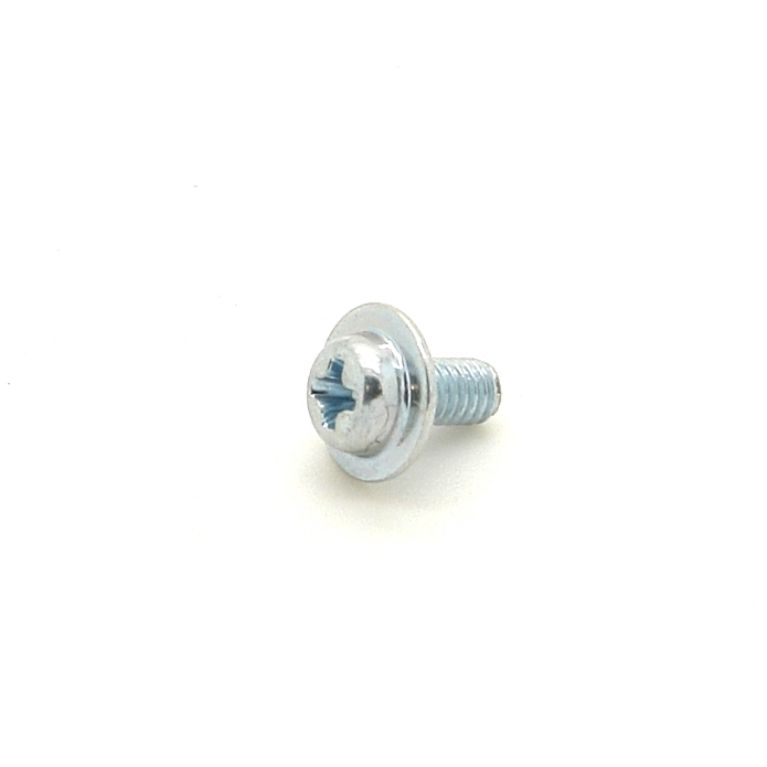 |
0.32 | |
| 8x Washer | 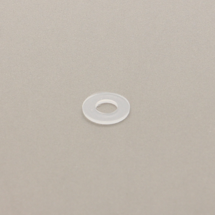 |
0.24 | |
| Dupont Jump Wire male/female | 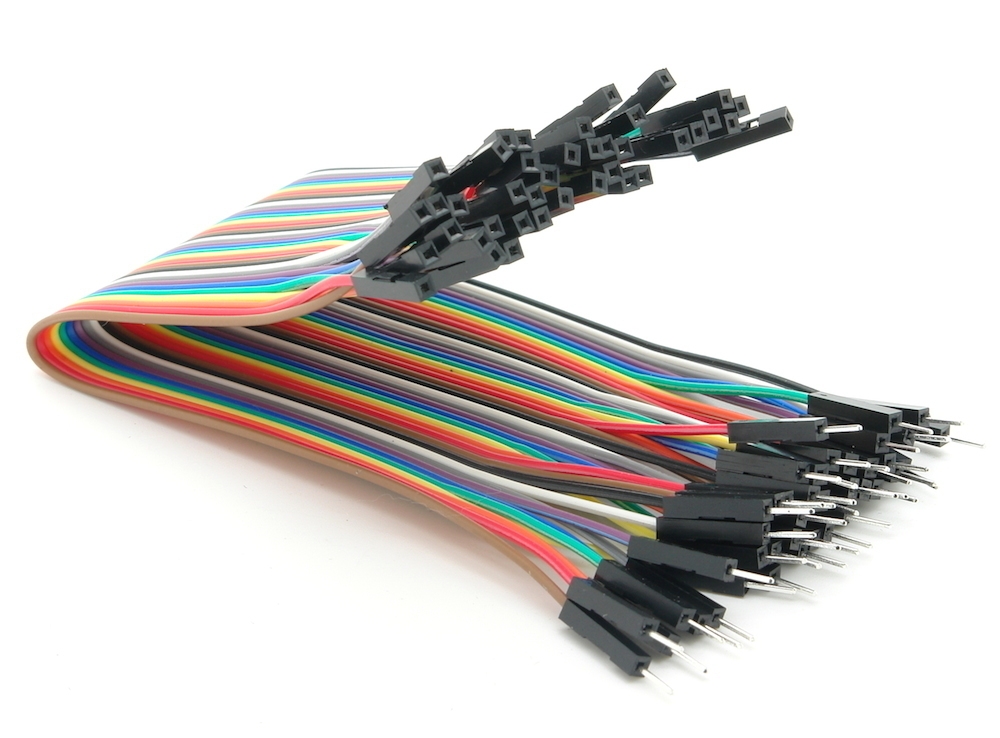 |
2.90 | |
| Braided Copper Wire |  |
0.69 | |
| Switch |  |
0.55 | |
| Push Button |  |
0.48 | |
| 1x LED |  |
0.10 | |
| 1x 1K Ohm Resistor |  |
0.06 | |
| Case |  |
Possibilities are limitless. :-) See MiczFlor/RPi-Jukebox-RFID#5 (beware, very long loading time) for some inspiration. | |
| Figures |  |
Optional. In case you wanna have physical objects you can attach your NFC stickers to. Again possibilities are limitless. | |
| Links last checked 2026-01-24. |

Since the Hifiberry Amplifier will take the whole multi-pin connector on the upper side of the Raspberry Pi, we will have to solder all the other connections to the bottom side. So when it comes to pin numbering you will always have to think upside down. TODO: add photos
- solder the multi-pin connector to the Raspberry Pi, it's 40 pins, so a good warm-up ;-)
- cut 2 times the right length of speaker cable (or just standard copper wire) for the speakers
- dismantle and tin-coat all 8 ends
- solder the cables to the speakers (if you have speaker cable, the anode + is usually marked in red)
- there is a 8-pin connector for the NFC reader board, that we need to solder
- depending where and how you wanna put the NFC reader in you case later, you have do decide to which side of the board the connector should face
- solder 8x the male side of jump wire to the Raspberry Pi, also see https://github.com/ondryaso/pi-rc522#connecting
- pin 17 red (3.3V power)
- pin 19 orange (GPIO10, SPI MOSI)
- pin 21 green (GPIO9, SPI MISO)
- pin 23 yellow (GPIO11, SPI SCKL)
- pin 18 brown (GPIO24, IRQ)
- pin 20 black (GND)
- pin 22 blue (GPIO25, RST)
- pin 24 white (GPIO8, SPI CE0)
- connect 8x the female side of the jump wire to the NFC reader
- SDA white
- RST blue
- GND black
- IRQ brown
- SCK yellow
- MISO green
- MOSI orange
- 3.3V red
- note: depending on which range you will have to span in your case, you might either want to buy longer jump wire or simply connect 2 jump wires one after another
- first solder the resistor to the LED, since they are connected in series it doesn't matter which side (anode + or cathode -)
- cut 2 times the right length of copper wire, the length depends on what ranges you will have to span in your case later
- dismantle and tin-coat all 4 ends
- first solder one cable to the open end of the LED, and the other cable to the resistor that is already connected to the led
- now when soldering the cables to the Raspberry Pi, you will have to consider the polarity of the LED
- the cathode (-) is the side with the slidely shorter pin that is also flat on the LED's head
- the anode (+) is simply the other side
- the cable on the cathode (-) side of the LED goes to pin 14 (GND)
- the cable on the anode (+) side of the LED goes to pin 8 (GPIO24, UART0 TXD)
- cut 6 times the right length of copper wire, the length depends on what ranges you will have to span in your case later
- dismantle and tin-coat all 12 ends
- solder one wire to each connector of the push buttons
- solder the free ends of the shutdown button to the Raspberry Pi
- pin 7 (GPIO4)
- pin 9 (GND)
- solder the free ends of the vol- button to the Raspberry Pi
- pin 29 (GPIO5)
- pin 30 (GND)
- solder the free ends of the vol+ button to the Raspberry Pi
- pin 33 (GPIO13)
- pin 34 (GND)
- polarity doesn't matter, they are just push buttons
- note: the buffering capacitors (and the inductor) are just used to cover scenarios where you wanna charge the powerbank while the Raspberry Pi is running (at the same time), when you're charging your powerbank with the Raspberry Pi switched off you may not need them
- to have our music box portable we've bouhgt a special kind of powerbank as power supply, they are called charge-through or pass-through powerbanks, they have the ability to deliver power and being charged at the same time
- also they do not need a button on the powerbank being pressed to activate power delivery
- however, almost all of these powerbanks I've seen cannot be used as uninterruptible power supply (UPS) directly
- when you unplug the external power supply after charging, they will discontinue to deliver power to the connected device they are charging for a very short moment, for a sensible Raspberry Pi this moment is too long and it will simply shut off and restart
- this is why we'll need a small buffer to cover those small interruptions
- TODO: how to wire the capacitors and inductor, this section is still in development
- simply mount the Hifiberry Miniamp aplifier to the multi-pin connector (that you soldered earlier) on the upper side of the Raspberry Pi
- the Hifiberry Miniamp uses following pins
- pin 12 (GPIO18)
- pin 35 (GPIO19)
- pin 36 (GPIO16)
- pin 37 (GPIO26)
- pin 38 (GPIO20)
- pin 40 (GPIO21)
- also see https://www.hifiberry.com/docs/hardware/gpio-usage-of-hifiberry-boards/
- download and install volumio: https://volumio.org/get-started/
- current version (Dec 2025) of Volumio is 4.x
- e.g. for linux:
- unzip the disk image
unzip Volumio-4.073-2025-12-05-pi.zip - this will create the image file
Volumio-4.073-2025-12-05-pi.img - insert the sd-card and find its device
lsblk - copy the image to sd-card, e.g.
sudo dd if=Volumio-4.073-2025-12-05-pi.img of=/dev/mmcblk0 status=progress
- unzip the disk image
- start, configure volumio, also see https://volumio.org/get-started/
- on the very first boot of Volumio and on a Raspberry Pi with on-board WiFi, Volumio will enable a Wifi Access Point called Volumio
- when Volumio boots up you should be able to see the Volumio AP, e.g. from your Laptop
- connect to the Volumio AP, the default password is "volumio2"
- open a browser http://volumio.local/ or http://192.168.211.1/
- do the Volumio setup wizard
- chose a language
- (re-)name your box, let's say to music-box
- important: later after reboot your box will not be available under http://volumio.local/ but http://music-box.local/
- configure audio output
- enable I2S DAC
- chose "HifiBerry DAC" from the list
- configure Wifi networking
- chose your home Wifi from the list and enter your Wifi password
- after reboot, Volumio will try to connect to your home Wifi
- skip the "add your music" step for now
- you're done, Volumio will prompt you to reboot your music box
- after reboot you should already be able to hear the Volumio startup sound when Volumio has booted up
- connect your laptop back to your home Wifi
- your laptop and your Volumio music box will now be in the same network
- the HifiBerry MiniAmp doesn't have a hardware mixer so you will have to
configure a software mixer in order to be able to control the volume
- open http://music-box.local/ in a browser
- goto "Playback Options" in the menu
- go down to "Volume Options"
- chose "Software" as mixer type and press "Save"
- the "Volume Options" will update after a short while
- now also configure a "Default Startup Volume", e.g. 60, press "Save" again
- in the main "Playback" screen of the Volumio web interface you will now be able to control the volume
- try play some music, in the main "Browse" screen there is "Web Radio" and then "Volumio Selection", just chose one of the radio stations to play, Volumio should now start to play the web stream of the radio station :-)
- goto http://music-box.local/dev
- press the "Enable" button for SSH
- the purpose of the MFRC522-trigger software is to detect NFS tags and call the volumio REST API to trigger certain actions; e.g. play playlists, stop playback, ...
- we will use Ansible to install the software on the Raspberry Pi, Ansible is an automation tool, if you wanna know
more about it have a look at https://docs.ansible.com/ansible/latest/index.html
- on your local machine (not the Raspberry Pi) clone the repo https://github.com/layereight/MFRC522-trigger
$ git clone https://github.com/layereight/MFRC522-trigger.git $ cd MFRC522-trigger/ansible $ vim inventory- replace the contents of the file inventory to point to your music box (e.g. music-box.local)
[my_pi] music-box.local ansible_user=volumio ansible_ssh_pass=volumio ansible_sudo_pass=volumio- execute the ansible playbook, it runs for roughly 12 minutes
$ ansible-playbook -i inventory MFRC522-trigger.yml ... - alternatively you can perform all the installation steps manually as described in the repo https://github.com/layereight/MFRC522-trigger
- on the network Volumio exposes a couple of samba shares (windows shares)
- e.g. on Windows in the windows explorer (the file manager) enter "\\music-box.local"
- on Linux (when your file manager has a samba plugin) enter "smb://music-box.local"
- one of the shares is called "Internal Storage"
- just copy your music files there
- Volumio will pick them up and add them to its music library automatically
- also see https://volumio.github.io/docs/FAQs/Audio_Sources.html the very last paragraph
- you can put your music, audio books, etc.
- Volumio is able to play a various amount of formats, see: https://volumio.github.io/docs/FAQs/General.html the paragraph "Readable formats"
- e.g. create one playlist per music album
- look for the keyword playlist in https://volumio.github.io/docs/User_Manual/More_first_steps.html
- ssh into your Volumio music box:
ssh volumio@music-box.local - the software should be running, check whether the software is running
$ ps awwwx | grep python
15269 ?        Ssl    0:03 python3 /home/volumio/devel/MFRC522-trigger/MFRC522-trigger.py
- hold 1 or 2 NFC tags against your NFC reader
- have a look a the MFRC522-trigger logfile, it should look something like this
$ cat ~/devel/MFRC522-trigger/MFRC522-trigger.log
2026-01-24 18:08:39,714 INFO Welcome to MFRC522-trigger!
2026-01-24 18:08:39,716 INFO Press Ctrl-C to stop.
2026-01-24 18:11:50,020 WARNING No mapping for tag 04:84:84:16:BC:2A:81
2026-01-24 18:11:54,392 WARNING No mapping for tag 04:84:84:16:BC:2A:81
- note the NFC tag ids
- edit MFRC522-trigger's config file:
vi ~/devel/MFRC522-trigger/config.json - change config.json accordingly, e.g. map NFC tag ids to Volumio playlists
- restart MFRC522-trigger
sudo systemctl restart MFRC522-trigger - hold the same NFC tags again against the reader, actions should be triggered now
- see the repo https://github.com/layereight/gpio-trigger
- trigger actions when you press the push buttons, e.g.:
- increase volume
- decrease volume
- trigger a system shutdown
- the MPU-6050 is a digital accelerometer and gyroscope
- the use of the MPU6050 module can be considered experimental and is totally optional
- it is used for additional control of the music box by motion gestures
- also see https://github.com/layereight/MPU6050-trigger
