-
Notifications
You must be signed in to change notification settings - Fork 458
WM331 Receiver Main Processor 3 in 1 board
Function
Variants
Parts
Programming
External interfaces
Service interfaces
Board view
Schematics
The board merges together three modules:
- Visual Positioning System - receiving and interpreting data from bottom camera and ultrasonic sonar for flight stabilization.
- Intelligent Flight - using data from cameras for collision detection and object tracking.
- OFDM transceiver - receiving commands from Remote Controller, and transmitting telemetry data plus compressed video stream for FPV.
The known variants are listed below.
| Marking | Overview |
|---|---|
| P02144.07 |
| Marking | Amt. | Pkg. | Function | Specification |
|---|---|---|---|---|
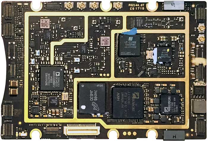
| Leadcore LC1860C P2F6 1017 026 INU086.00 ARM | 1 | Quad-core 1.5GHz ARM Cortex-A7 SoC with Mali-T628 GPU and LTE Cat 4 baseband modem | ||
| Leadcore LC1160 S2F2 4216 000 HA7451 | 1 | Power Management Unit and Audio codec, which meets LC1860 requirements | ||
| Micron 7HA98 JWB30 PFVP | 1 | Micron 4GB EMMC + 4GB LPDDR3 | ||
| Movidius MA2155 651-B1 133T | 1 | VF2BGA225 | Movidius Myriad VPU, 600MHz, PWM outputs; receives data from all cameras and allows machine vision for intelligent functions of the drone | description |
| Lattice LE-2100E 5MG256C-A646VV22 PHIL 1647 DL54C3944?017 | 1 | Lattice MachXO3LF FPGA with 2100 Look-Up Tables, 1.2V supply, high speed grade | datasheet | |
| 44641B BCL0TN 1703 | 1 | |||
| 85408-11 3033D34.1 1703 MX | 2 | SKY85408-11 High-Power (+23dBm) 5GHz Ultra-Linear WLAN Power Amplifier with Integrated Power Detector | description datasheet | |
| SKY85809 64055 1640 MY | 2 | |||
| SKY 5404 | 2 | |||
| 78Y | 2 | |||
| W1A 6n | 4 | 3-pin SOT-23 | PMBT3904 NPN switching transistor | description |
| T120 PDBC | 1 | Quartz oscillator, 12MHz | ||
| A0FYD | 1 | |||
| i1908 | 1 | |||
| PA 7CF | 1 | 3x3 UDFN/WSON | Mini Linear Regulator, DI AP7361ADJ | DI datasheet |
| S 81 | 4 | 6-lead 1.5x1.5 QFN-33 | SKY13320-374LF: 0.1-6.0GHz GaAs SPDT Switch | description |
| CHR | 1 | |||
| CEH | 1 | markings uncertain | ||
| 5E???? | 1 | markings uncertain | ||
| AD80403BBCZ #1651 3692772.1 Singapore | 1 | 144-ball 10x10 CSP-BGA | 2x2 RF agile transceiver, Band: 2.4GHz to 2.5GHz and 4.9GHz to 6GHz; tunable channel bandwidth: <200kHz to 40MHz; Lightbridge RF amplifier | brief |
| NS 71A0F7U K00105 | 1 | National Semiconductor | ||
| K20 6273P | 1 | Quartz oscillator | ||
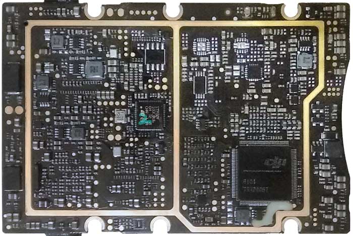
| STM32F 103CBU6 GH??2 93 CHN 639 | 1 | Mainstream Performance line, ARM Cortex-M3 MCU with 128Kbytes Flash, 72MHz CPU, motor control, USB and CAN; Lightbridge MCU | description | |
| T120 PD9Y | 1 | Quartz oscillator, 12MHz | ||
| DJI R101 751?995T | 1 | Lightbridge digital data encoder/scrambler; handles input and output data streams of the RF transceiver | ||
| 2.2 | 4 | SMD inductor, 2.2nH | ||
| 1R0 | 1 | SMD inductor | ||
| A??? | 6 | 8-pin SOT23 | Buck converter |
| Chips | Firmware | Description |
|---|---|---|
| LC1860C | m0801, but see m0901 | Intelligent flight and obstacle avoidance. The module identifier is m0801, but in later platforms was renamed to m0901. |
| MA2155 | m0802 | Collision avoidance and sensory support for intelligent flight functions. |
| LCMXO3L | m0803 | Real-time digital processing for intelligent flight functions. |
| STM32F103 | m0900 | Lightbridge MCU; configures and drives data encoder and WiMAX transceiver. |
The board contains connectors:
| Marking | Overview |
|---|---|
| TODO |
The following service pads exist on this board:
| Marking | Overview |
|---|---|
| GND | Ground |
| TX | UART Transmit line of the LC1860 console |
| RX | UART Receive line of the LC1860 console |
| TODO |
Top of a P02144.07 board:
Bottom of the P02144.07 board:
flowchart LR
    FFC-Encoder((FFC to<br/>Encoder))
    FFC-Encoder===Processing-SoC
    subgraph Receiver Main Processor 3-in-1 board
    Processing-SoC[LC1860C SoC<br/>Quad-core<br/>ARM Cortex-A7]
    Data-Scrambler[Dji ASIC<br/>data encoder/<br/>scrambler]
    Lightbridge-MCU[Lightbridge<br/>MCU]
    WiMAX-Transceiver[WiMAX<br/>double<br/>transceiver]
    Lightbridge-MCU-- tx config<br/>and DUML ---Data-Scrambler
    Lightbridge-MCU-- radio config<br/>via SPI ---WiMAX-Transceiver
    Processing-SoC===Data-Scrambler
    Data-Scrambler===WiMAX-Transceiver
    WiMAX-Transceiver===RF-Tx-Amp-A[RF power<br/>out amp]
    WiMAX-Transceiver---RF-Rx-Amp-A[RF LNA<br/>inp amp]
    WiMAX-Transceiver===RF-Tx-Amp-B[RF power<br/>out amp]
    WiMAX-Transceiver---RF-Rx-Amp-B[RF LNA<br/>inp amp]
    RF-Switch-A[RF<br/>switch]
    RF-Switch-B[RF<br/>switch]
    RF-Tx-Amp-A===RF-Switch-A
    RF-Rx-Amp-A---RF-Switch-A
    RF-Tx-Amp-B===RF-Switch-B
    RF-Rx-Amp-B---RF-Switch-B
    end
    Antenna-A1((Ant))
    Antenna-A2((Ant))
    Antenna-B1((Ant))
    Antenna-B2((Ant))
    RF-Switch-A---Antenna-A1
    RF-Switch-A---Antenna-A2
    RF-Switch-B---Antenna-B1
    RF-Switch-B---Antenna-B2
Thick lines present propagation of video data. The live video feed comes from Camera Encoder board through Flex Film Cable. The Leadcore SoC (LC1860C) processes it and prepares input data for the ASIC scrambler for the Lightbridge protocol (DJI R101). That scrambler contains DJI IP with synthesis the digital part of Lightbridge protocol. The scrambler prepares video data and telemetry to be sent through radio channel, and supplies it to WiMAX Transceiver (AD8040), from where the modulated signal is amplified and sent toward antennas.
The antennas can also receive DUML packets from the RC, in which case the input RF signal is amplified through LNA, received through WiMAX Transceiver, and provided to the ASIC scrambler for error correction and unscrambling. The DUML packets are provided to the Lightbridge Main Controller Unit, and from there routed to other modules of the drone.
The MCU micro-controller is responsible for configuring the transmission by sending SPI commands to the WiMAX Transceiver, and setting logic signals on some configuration lines of the ASIC scrambler.
flowchart LR
    FFC-Encoder((FFC to<br/>Encoder))
    FFC-Encoder====Processing-SoC
    FFC-Sensors-Down((FFC<br/>to Down<br/>Sensors))
    FFC-Sensors-Forward((FFC to<br/>Forward<br/>Sensors))
    FFC-Sensors-LSide((FFC<br/>to L Side<br/>Sensors))
    FFC-Sensors-RSide((FFC<br/>to R Side<br/>Sensors))
    FFC-Sensors-Down---Movidius-SoC
    FFC-Sensors-Forward---Movidius-SoC
    FFC-Sensors-LSide---Movidius-SoC
    FFC-Sensors-RSide---Movidius-SoC
    subgraph Receiver Main Processor 3-in-1 board
    Processing-SoC[LC1860C SoC<br/>Quad-core<br/>ARM Cortex-A7]
    Inteligent-FPGA[LCMXO3L FPGA<br/>2100 LUT]
    Inteligent-Xlat(quartz<br/>oscillator)---Inteligent-FPGA
    Processing-SoC---Inteligent-FPGA
    Movidius-SoC[MA2155 SoC<br/>Myriad VPU]
    Movidius-SoC---Movidius-Xlat(quartz<br/>oscillator)
    Processing-PMU[LC1160 PMU<br/>for Leadcore]
    Movidius-SoC---Processing-SoC
    Processing-PMU---Processing-SoC
    Processing-SoC---Processing-RAM-EMMC[4GB eMMC<br/>4GB lpDDR3]
    Processing-Xlat(quartz<br/>oscillator)---Processing-SoC
    end
    FFC-Flight-Control((FFC<br/>to Flight<br/>Control))
    Processing-SoC----FFC-Flight-Control
No schematics available.
This page is created by drone enthusiasts for drone enthusiasts.
If you see a mistake, or you know more about specific subject, or you see an area for improvement for the wiki - create an issue in this project and attach your patch (or describe the change you propose).

